
Curve Continuity
Continuity in piecewise Bézier curves was one of the important topics of our first-year architecture geometry course. Here, I will briefly summarize what this course attempts to convey. Since there are many ways to define it, I have summarized them below and tried to indicate how each is perceived visually.
C0: Position Continuity
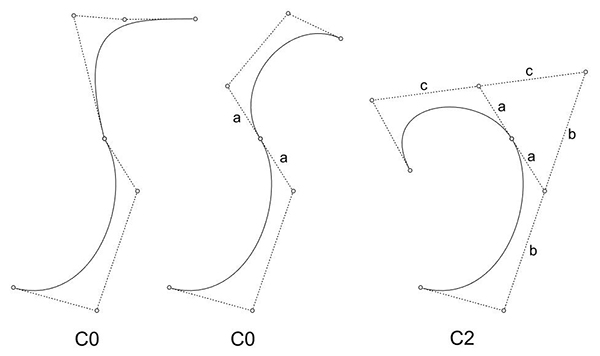
This refers simply to the end-to-end connection of two Bézier curve segments; there are no gaps between the curves. The endpoint of the first curve is on the starting point of the second curve. The curve is geometrically continuous, but a sharp break (corner/kink) may exist at the joint. Tangents and curvature are not compatible.
C1: Tangent Continuity
Beyond positional continuity, this ensures that the tangent vectors at the junction point are also equal in direction and magnitude. Thus, the first derivatives are continuous. The first derivative vector at the end of the first curve equals the first derivative vector at the start of the second curve. The control point preceding the joint, the joint itself, and the subsequent control point lie completely on the same straight line (collinear), and the distances between them are equal. The visual result is a smooth transition. However, because curvature continuity is not yet established, a sudden change in the radius or intensity of the curvature (acceleration/jerk) can be observed. If you turn on the control points of both curves and look at the segments of the joining control polygon, we can say that C1 exists between these two curves if they lie on the same line and are of equal length.
C2: Curvature Continuity
C2 (curvature) continuity of two Bézier curves requires equality of the second derivatives. At the junction point of the curves, not only the tangent vectors, but also the curvatures are equal and connected smoothly. As seen in the visual, a 1:1 ratio is established between the control points at the junction points to form an “A-frame” over the apex. These ratios mathematically guarantee the continuity of the second derivatives (curvature continuity). The knot or parameter intervals k, k+1, and k+2 ensure a smooth transition between two neighboring Bézier segments. You can use whichever of these definitions you prefer. The one that interests me the most, of course, is the visual and geometric one. That is, not only do the control polygon segments tangent to both ends need to be in the same direction and of equal length, but the segments of the A-Frames on top of these segments must also be of equal length. What does this mean?
The Exercise
This must be the most fun exercise of the course. If this is the most fun part of the course, imagine the rest :) How can we draw a C2 continuous curve for any given curve? I tried to show this step by step below. To geometrically construct C2 continuity using the A-frame method (without using commands), the line passing through the last two control points of the existing curve is extended beyond the junction point, and equal 1:1 distances are marked along this axis to determine the tangent control point (C1). Then, the top apex control point is placed over these points to form a triangle (A-frame), creating a visually flawless curvature transition without requiring any commands or formulas. The first three control points of the second curve are now ready in our hand. We can place the fourth and final control point wherever we want. The resulting 3rd-degree Bézier curve will have C2 continuity with the first curve.
Rhino Tools
In Rhino (tested in Rhino 8), commands that establish continuity include MatchCrv, BlendCrv, FilletCrv, and ChamferCrv. Their counterparts for surfaces can be observed in MatchSrf, BlendSrf, NetworkSrf, and Sweep2. Analysis tools related to continuity include GCon (Geometric Continuity) and CurvatureGraph. CurvatureGraph opens a display called a curvature comb. In C1, there is a jump in the comb’s length; in C2, the comb is continuous but has a slope break; in C3, the comb also looks smooth. Additionally, Zebra, EMap, and CurvatureAnalysis (for surfaces) can be mentioned. ShowCP / PointsOn, Rebuild, ChangeDegree, and InsertKnot can be used to display the control point layout and control the degree. I tested these in Rhino 8, and there may be new features in the newly released version 9.
Cite this post
Related Posts
B-Spline Decomposition
February 6, 2024
This is a short video tutorial on the B-Spline decomposition I studied earlier here. This tutorial demonstrates how to decompose a B-Spline curve into Bezier curves using Rhino. Despite the original Bezier-de Casteljau algorithm requiring degree+1 control points, Rhino allows drawing a degree-3 curve with any number of control points. By examining knot points and dividing segments appropriately, the B-Spline curve can be manually subdivided into Bezier curves. This involves placing control points, dividing segments, and connecting points in a…
Parametric point on a Bezier curve
February 1, 2024
In this short tutorial, I am going to show you how to locate a parametric point on a Bezier curve. This will be a third-degree cubic Bezier curve. So, I start by placing four control points. I name these points from P0 to P3. Then, I connect them by a polyline in order. I explode the polyline into the segments. The parameter of my point must be a number between 0 and 1. I will divide the segments, so I…
Guitar Shape
November 2, 2026
Traditionally, when shaping a guitar form, a luthier relies on a combination of craftsmanship and precise geometric tools. This process involves mastering wood-bending techniques around rigid molds, guided by physical templates to achieve the desired acoustic and aesthetic curves. Curves, once more I love talking about this so much. Could my obsession with Bézier curves be OCD? The history of curved shape construction reflects a transformative journey from physical craftsmanship to sophisticated digital computation, primarily driven by the demands of…
I realized this method of constructing basis splines from given control points while searching for a way to teach students about basis splines. I couldn’t find an easy and visual method to create clamped basis splines by connecting simple cubic Bézier spans. It is a tough job and requires lots of complex equations. However, I suddenly realized that there is a special way of doing that. So I decided to share this with the people searching for an easy way…
Curvature Approximation by Drawing
March 14, 2024
Curvature can be roughly described as how much a curve is “turning” at point a P. We place two “very” close tangents and measure the difference between them. The closer these tangents are, the more precise our approximation would be. An osculating circle is a tangent circle that has the same curvature as the curve at point P. The larger the circle, the more “flat” the curve is. An infinitely large osculating circle means the curve is linear at point…