
Terrain Modeling
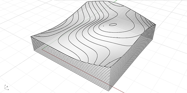
Here is a short tutorial on getting help from Grasshopper in physical terrain modeling. It is a classical architectural terrain modeling process. Let’s see how Grasshopper can help us with this.
Part 1: Terrain modeling for Laser cutter
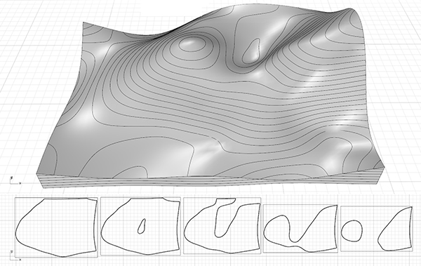
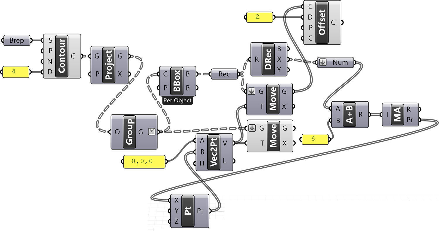
The terrain model entered in the Brep data store in this application is a closed/solid model. For now, you can also use ready-made components such as Cone or Sphere (Sph) to quickly produce a solid model. In this application, after we obtained the section curves with Contour, we created the projections of these sections on the ground plane with the help of the Project component. We recommend that you examine the data tree in the output of the Project component. Because with this data tree, we can group curves in each section plane easily. After the projections are grouped with the help of the Group component, the dimensions of each group are determined by the Bounding Box (BBox) component.
We converted frames limiting the sections into rectangles with the help of a Rectangle (Rec). Then, we obtained the dimensions of the rectangles numerically with the help of Deconstruct Rectangle (DRec). The size of the rectangles in the X direction gives information about how far each of our cut sheets is to be brought side by side. The Deconstruct Rectangle (DRec) component has generated data of the data range (domain) type. To quickly find out what width this range corresponds to in terms of distance, we connect the range data with the Number (Num) parameter and convert the range to a number. This is again GH’s pleasant surprise.
Preparing the Laser cut Sheets
To figure out how far to offset each sheet, we finally resort to the Mass Addition (MA) component, which adds up these widths. We’re in luck because this component not only gives the sum of a large number of numbers but also the subtotals we want. Thanks to this output, we can obtain all intermediate results in a list structure. Such as the addition of one and two index numbers, one, two, and three index numbers. We shift our sections with the help of this list obtained from the Pr output. As a fine adjustment, a little Offset has been added so that rectangular shapes can be cut easily. In addition, an addition (Addition (A+B)) has been made to the dimensions of the rectangle in order to keep the sheets slightly apart from each other.
Part 2: More Advanced Version
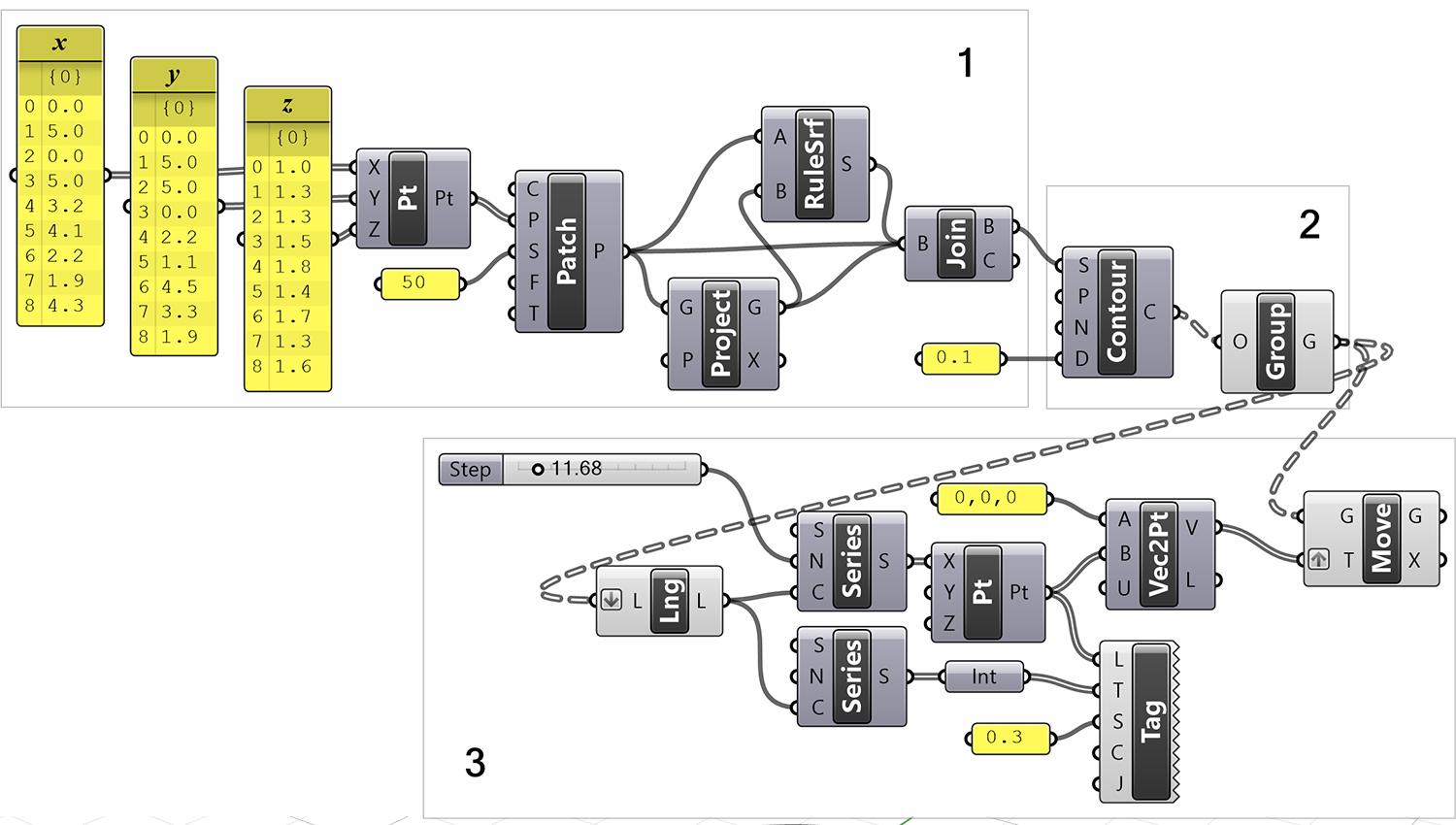
In this second application, we complete the model that we tried before. We can examine this application in three parts. In the first part, we transform the points whose coordinates come from the separate lists to the surface with Patch and complete the missing surfaces in order to turn this surface into a solid object. There are two ways to do this. First, after extruding our land surface downwards, it can be to delete the parts below from the Z=0 plane. We can use boolean operations for this. Another method is in the form of completing and combining the missing surfaces, the projection of our land surface to the ground plane. We used a Ruled Surface (RuleSrf) to make the four surfaces on the edges. Instead of the A and B curves, we entered the lower and upper edges of the surfaces.
Although we connected our surfaces to an input that requested curves, the edges of the surfaces had no error. Finally, we joined all our surfaces with the Brep Join (Join) component. You can examine the output of Brep Join (Join) B to see if the result is really a solid object. The closed brep statement will show that everything is fine.
Final Touches for the Terrain Modeling
In the next part of the application, we took the contour curves and grouped them. In the third part, we made these curves ready for cutting using the components we learned earlier. Again, we created vectors using the Move component. In addition, we numbered the sections.
Cite this post
Related Posts
Site Modeling
March 26, 2015
Site models could be calculated for laser cutting easily using Grasshopper’s native components. This definition was a practical one we created in the Parametric Modeling course to see that Grasshopper could also be utilized to prepare fabrication documents not generating design outcomes. However, this definition is a draft one and could be improved more by putting labels inside of each cut piece, trimming the edges properly and so on. It is good news for students at least that they have a…
Open Nest
July 24, 2023
In this short trial, I will be testing the Open Nest add-on for Grasshopper. The add-on is available in food4rhino as of 2023. For this test, I will use the latest exercise on Interlocking structures I experimented with here. Nesting is an important topic, especially in today’s economic crisis. It reduces the waste materials on laser-cut plates. First, I should re-visit the interlocking structures Grasshopper definition here. The below image is the new definition for the interlocking structure: The new…
Contouring Update
March 17, 2015
After this tutorial, we are still working on the basic ways of making contouring easier in Grasshopper. This is the updated version of the 2-year-old contouring definition in Grasshopper, with some additional functionality. It produces a flat and properly numbered output for each section. However, it does not include optimized nesting to reduce material use.
Testing the Nesting
May 28, 2012
Here I am testing the nesting. RhinoNest is a plug-in for Rhino and a set of components for Grasshopper. I tested it using my old interlocking fabrication definition (here) and (here). I downloaded RhinoNest from this website and installed it. However, I sounded a little complicated at first sight. Then I found a sample definition (here) and modified it a little bit to meet my purposes. First of all, I added orientation components (grey group below) to align all sections to the WorldXY…
Shear Magic
March 7, 2015
This video is dedicated to Design Computing and Basic Design students, who “contour” and then move each section by hand in Rhino. They do it individually to fabricate their laser-cut homework from cardboard. It could also be a macro but I prefer this. Because it does not work in all conditions. Maybe you should orient your contouring results similar to those shown in the video, and then use the shear command to spread them. I called this method “shear magic”. Let’s…