
RHWC of Convex Polyhedra
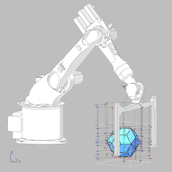
Hot-wire cutting (HWC) is a cost-effective subtractive fabrication technique used across many industries. The basic idea of HWC is to cut a block of material by melting it with a resistance-heated wire under tension. It is effective for materials with low melting temperatures, such as expanded polystyrene (EPS) and extruded polystyrene (XPS). Generally, HWC is associated with mold production in the architecture, engineering, and construction (AEC) industries. Robotic hot-wire cutting (RHWC) is a subtopic of HWC. In a standard RHWC setup, the robotic arm either guides the cutting wire or holds the material block and moves it around a fixed wire. Cutting performance is highly sensitive to the interaction between wire temperature, cutting speed, and material density. In this post, I will propose a novel toolpath algorithm for the RHWC of convex polyhedra. The robot maneuver strategy was composed of four steps for each face of the polyhedron:
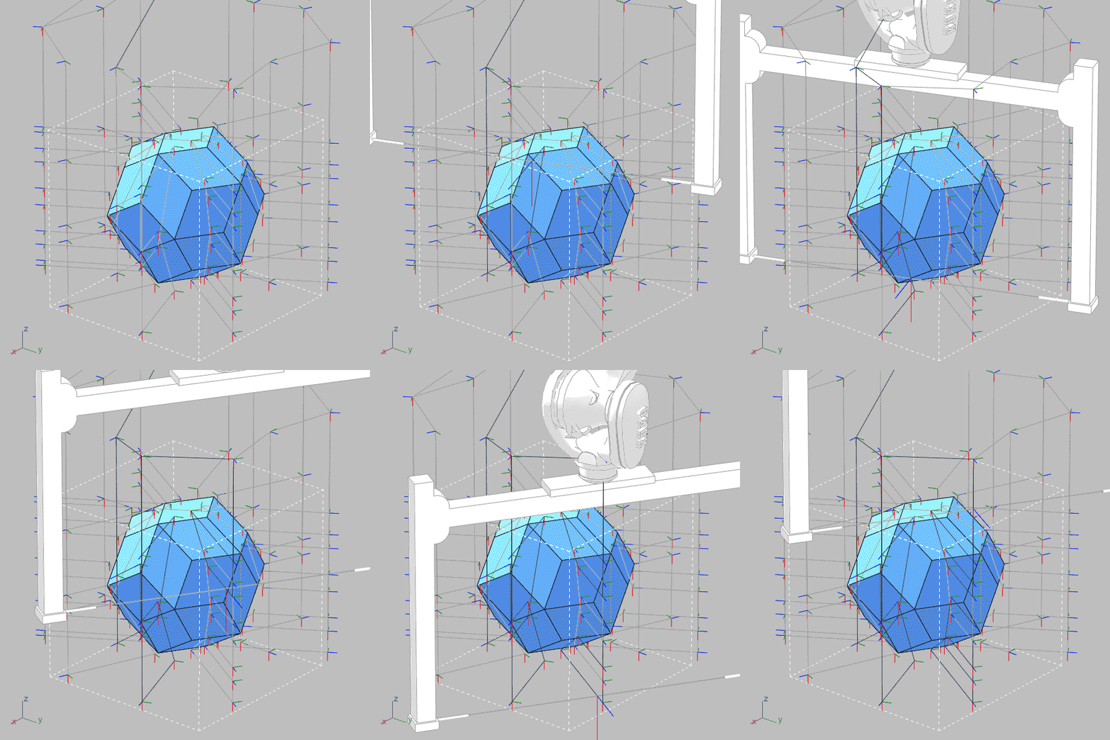
- Entry: The entry step is the inward movement from the approach point to the cut’s starting position. The wire enters the block and reaches the previously calculated starting position.
- Approach: The robot will approach the EPS block from the top down to align with the entry level.
- Cutting: The wire performs a linear sweeping motion at the cutting speed along the face plane, to the ending position.
- Exit: The retraction maneuver involves moving the wire out of the block to a safe distance from the ending position using a vector generated via the same method as the entry maneuver. Then, the process will continue with the approach maneuver for the next face.

Polar Face Sorting
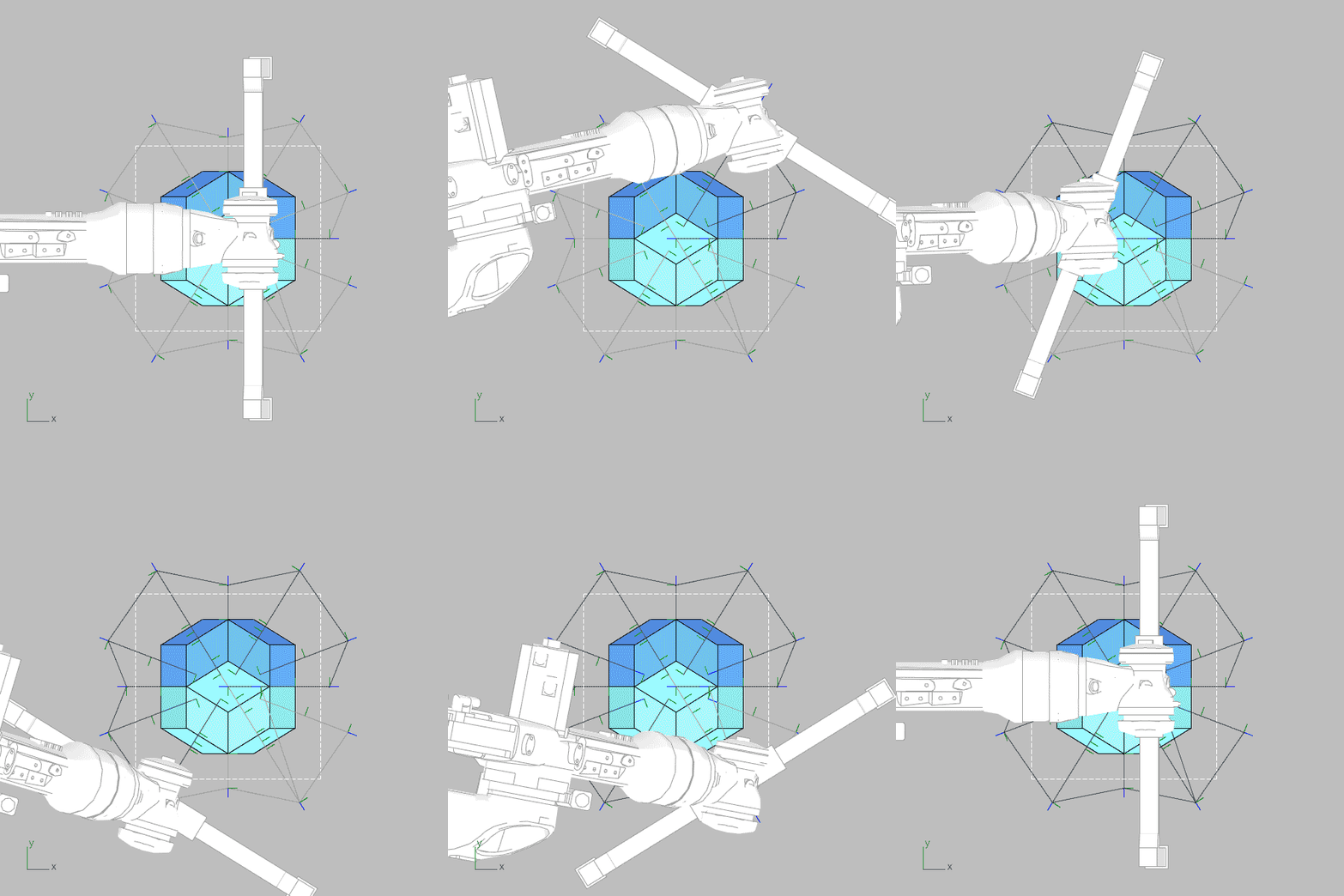
One of the most critical issues in the algorithm is the face sequencing. Because it is highly likely that the axis limits of the robotic arm will be challenged if the faces are chosen randomly. This is why I developed a Polar Face Sorting (PFS) algorithm to access all faces by only a single full revolution around the shape. To do that, the geometric centroid of the shape is defined as the origin. For each face, the geometric centroids are projected onto the World-XY plane. Then, these projection vectors are sorted polarly in a clockwise (or counterclockwise) direction.
In Grasshopper, I solved this at the start of the algorithm by sorting all the faces. I did that by pulling all centroids on a circle and then reading the parameter on that circle. Other methods, such as the Vector Angle component, brought issues with + and – angles. At the beginning of the operation (at the home position), the A6 axis is moved to -180 °. When all faces are finished, the robotic arm would make a single revolution around the shape. The process is completed by processing all faces before the A6 axis reaches the +180° limit.
Cutting Planes
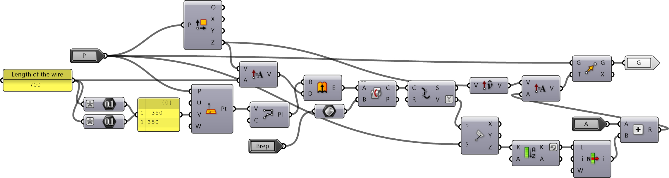
From previous production experiments, I knew that the uneven wire speeds reduce surface quality. I needed a single linear sweeping motion from top to bottom at a constant speed and angle while cutting the faces. This requires calculating the plane that is parallel to both the ground plane and the face to be cut. I did that by adding a Python component.
I spent a lot of time figuring this out in Grasshopper first, only to realize later that I was simply doing a Cross Product. This Python component performs a geometric transformation that realigns a plane relative to the world Z-axis. First, the cross product of the vertical direction with the plane’s normal vector was calculated to create a new horizontal X-axis parallel to the ground. Then, the plane’s normal and this new X-axis are crossed again to generate a Y-axis aligned with Z, following the right-hand rule. All axes are normalized, forming a new plane around the original origin.
import Rhino.Geometry as rg
origin = P.Origin
n = P.Normal
zw = rg.Vector3d(0, 0, 1)
x_axis = rg.Vector3d.CrossProduct(zw, n)
if x_axis.Length < 1e-6:
    x_axis = P.XAxis
else:
    x_axis.Unitize()
y_axis = rg.Vector3d.CrossProduct(n, x_axis)
y_axis.Unitize()
O = rg.Plane(origin, x_axis, y_axis)
The resulting plane lies within the face plane and is perpendicular to the ground normal at the same time. This process ensures a clean and high-quality cut while effectively reducing the number of active robot axes from six to five.
Escape Planes
Once the planes to be swept and cut were calculated, I also needed to generate planes to align and retract after cutting. For this, I used a cluster because the same process had to be repeated twice in reverse. This calculation, which is also tied to the dimensions of the EPS block, was quite fun in its own right. You can open the cluster to see what is going on inside. I had to jump through quite a few hoops here to make sure the wire completely cleared the block. In the end, the robot approaches all cutting planes and exits without colliding with the block
Experimental Productions
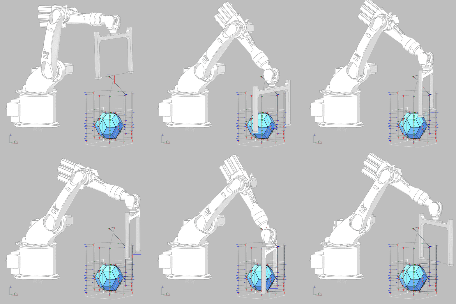
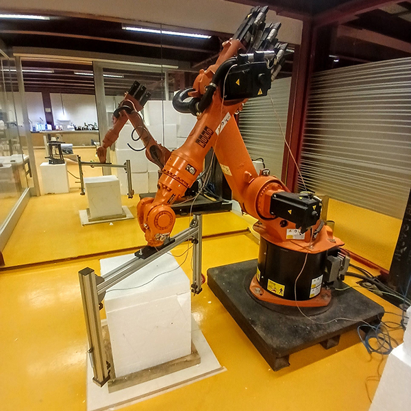
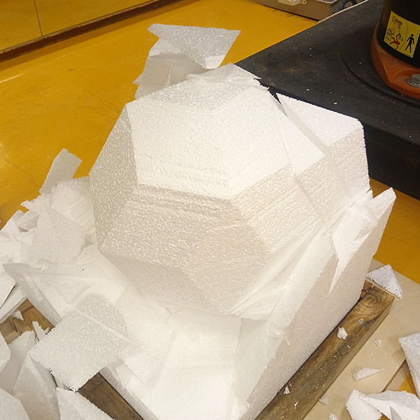
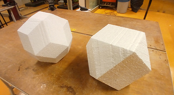
A six-axis robotic arm (Kuka KR-20) was used for simulations and experiments. The frame of the cutting tool was made from 40 mm aluminum sigma profiles measuring 541 x 790 mm. The cutting wire was a nickel-chromium alloy measuring 690 mm in length and 0.4 mm in diameter. To maintain the tension despite thermal expansion, the wire was attached to a spring at one end of the frame. The Tool Center Point (TCP) of the HWC was the middle point of the wire, which is located at the coordinates relative to the flange; x, y, z = (0, 0, 438) mm, and A, B, C = (0°, 0°, 0°). The power supply used was a 30 V, 10 A adjustable unit. After several trials, we used an optimal voltage of 24 V (an average current of 2.6 A) to balance cutting speed and kerf width. Low-density (12 kg/m3) EPS foam blocks were used in the experiments. These blocks were placed in front of the robotic arm, centered at the base coordinates of (1000, 0, -150) mm. This position enabled the HWC to move and rotate freely, minimizing the risk of colliding its frame with the arm. Here are the results of the cutting experiments:
Conclusions
Path planning for RHWC is an interesting topic. Even relatively simple geometric forms can quickly become complex when subjected to kinematic constraints. I also experimented with other face sequencing methods. For example, within the computational geometry literature, the problem of unfolding polyhedral surfaces has been theoretically established through works such as Demaine et al.’s Zipper Unfolding. However, rather than pursuing purely geometric shortest paths, the proposed algorithm incorporates joint limits and potential collision scenarios as major design parameters. I haven’t tested this code with different or irregular polyhedra yet. I’m planning to develop it further.
Cite this post
Related Posts
Robotic Hotwire Cutting Polyhedra
December 20, 2018
Today, we have studied creating complex robot programs manually again. Platonic solids were the subject of this study. Students tried to create a sequence of robot moves that produces a Platonic solid out of a 17cm EPS cube. We simply call this the robotic hotwire cutting polyhedra exercise. However, the size of our hotwire cutter became one of the problems because of its risk of crashing. We crashed several times but managed to cut some polyhedra at the end of…
Robotic Earthcrafts III
August 16, 2026
Last month, we completed the third edition of the Robotic Earthcrafts workshop series, which I co-organized with Fulya Akipek, following the first in 2018 and the second in 2023. An earthen mixture composed of clayey soil, lime, fibers, and cement was rammed into molds produced via robotic hot-wire cutting. The geometry of the fabricated wall is based on a hexagonal grid and features a Truchet-like variation. Constructed using four different block types, the wall was completed within 5 days and…
This is the new paper with Meryem Nurefşan Yabanigül, published at Automation in Construction. It is also Meryem’s master’s thesis. This study is about testing the production of curved surfaces with non-linear robotic hotwire cutting and shape memory alloys. Below is the abstract of it: Robotic arms are being used by construction firms and schools of architecture around the world in design/build research and material studies. Some of these studies utilize robotic hot wire cutting (RHC) as an efficient production…
Robotic Fabrication Student Project: Micro-Wave
March 21, 2019
This is a robotic fabrication student project developed in the Digital Fabrication elective course in 2018. This group of students experimented with the hot wire cutting of EPS foam. Their aim was to create curved surfaces by using a straight wire. Design research started with a literature study of precedents. Then, after several cutting experiments with the available hotwire cutter tool, they gained better control over the technology. However, they found the available tool too large and inefficient. They decided…
PLURA Pavilion
September 22, 2026
Last year, during the first stage of the Architectural Design Graduate project, our student team made a quick preparation and participated in the experimental works exhibition at the International Antalya Architecture Biennale (IABA 2025). This was a challenging yet educational process for our team. Using EPS foam and the robotic hotwire cutter (RHWC), a production run of 125 units, consisting of two modules (95 octahedra and 30 icosahedral units), was carried out. The icosahedral units also underwent an additional cutting…