
Tool Calibration in Robots
On the second day of the Digital Fabrication course, we tried to understand what is a “tool” and how to draw/ produce/ attach/calibrate a simple penholder tool for our robot. This study will hopefully make students aware of the effects of these procedures in robotic design and fabrication.
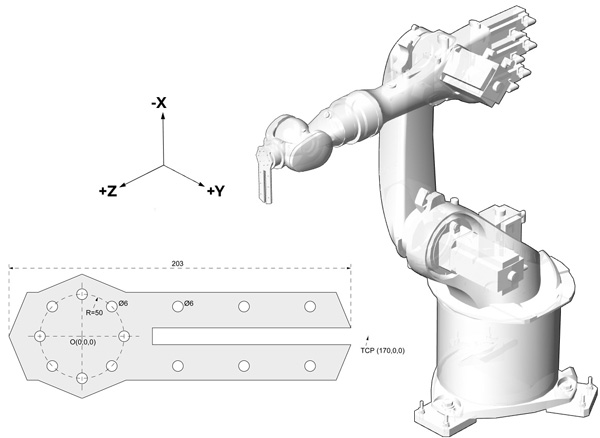
The tool we used here is based on this Rhino drawing laser-cut from a waste plexiglass sheet. The flange of our robot has a diameter of 50mm and has 8 holes for screws with a 6mm diameter. I also left some other holes to fix a pen with zip ties. In the exercise, first, we familiarized ourselves with the axis and Cartesian motions via smart pad. After remembering the last week and getting comfortable with the manual jogging techniques, we calibrated the penholder tool by using the 4-point method described in the robot’s manual.
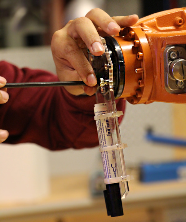
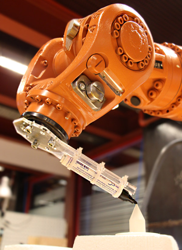
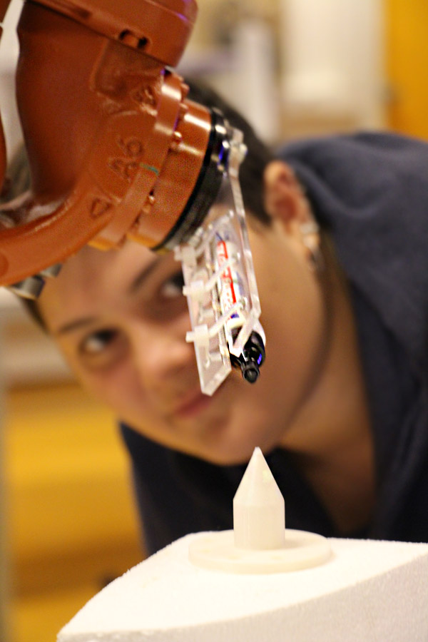
We analyzed the drawing of the tool and determined a TCP (tool center point) position, which is precisely 170mm far from the flange center. This drawing also constitutes the front view of the flange coordinate system. After calibrating the tool by using the 4-point method, we checked the calculated position of the TCP (should be less than 2mm.) Also, check the position of TCP by placing a point on that coordinates in Rhino. Kuka calculated the TCP as 169.1 mm far from the flange center. This is less than a millimeter and perfectly enough for us.
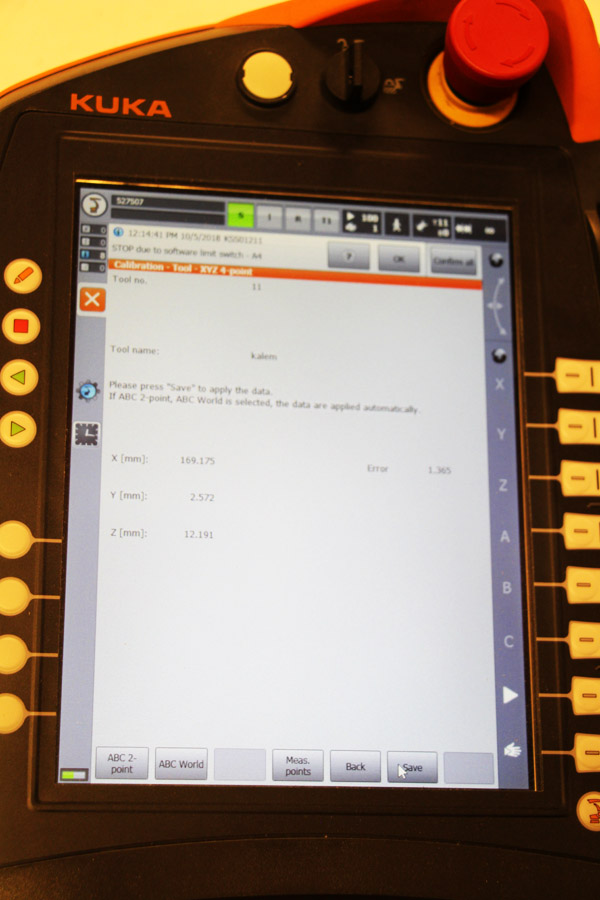
We used the tool coordinate system for manually jogging the robot. If the calibration is correct, the robot should be able to move towards its flange direction by Z-axis and towards the direction of the penholder by the X-axis. Finally, we tried to draw points and lines on various foam board surfaces by using those axes.
Cite this post
Related Posts
Robotic Chopstick Digger Exercise
November 5, 2018
Today, we tried to understand one of the ways of generating multiple planes in Grasshopper. This is an important step in utilizing the robot program efficiently. Instead of manually jogging the robot, we designed the path that the robot will dig lots of chopsticks. In the “Robotic Chopstick Digger Exercise”, every student designed their own paths and decided the height, orientation, and number of sticks to be dug on an EPS block. I provided the Rhino and Grasshopper files with…
Robotic Chopstick Digger
October 29, 2018
Today in the Digital Fabrication course, we examined digital-physical translations utilizing the robots add-on for Grasshopper. Students learn how to get coordinate data from a physical environment, use it in the digital model and apply it to a robot motion. We aimed to dig chopsticks into an EPS block by using a special wooden tool called “Chopstick Digger”. In the first hour of the class, we attached the “pointer” tool, which is already calibrated to the robot. Students used “Actual…
Parametric Tool Designer for KUKA PRC
August 7, 2024
In architectural research, a significant challenge in robotic fabrication is replicating setups due to the unique configurations used in each study. There is a lack of a unified software platform connecting various researchers and their robotic setups. Additionally, the fabrication tools are typically not open-source and may not be versatile across different scenarios. I suggest using Grasshopper’s parametric modeling capabilities to address these challenges to create flexible robotic tools. Specifically, I’ve developed a definition that allows the design of tools….
Basics of Robot Programming
October 24, 2018
Today, we started learning Robots add-on for Grasshopper. The first two codes we experimented with were similar to the first week’s jogging exercises. In the first one called “axial jogging”, we had 6 number sliders to control the angles of the axes. Every number slider generates values between -Pi and +Pi. These numbers are joined into a text by adding a comma in between. Then, Create program and Simulate Program components of the Robots plug-in are used to convert this…
RHWC of Convex Polyhedra
September 12, 2026
Hot-wire cutting (HWC) is a cost-effective subtractive fabrication technique used across many industries. The basic idea of HWC is to cut a block of material by melting it with a resistance-heated wire under tension. It is effective for materials with low melting temperatures, such as expanded polystyrene (EPS) and extruded polystyrene (XPS). Generally, HWC is associated with mold production in the architecture, engineering, and construction (AEC) industries. Robotic hot-wire cutting (RHWC) is a subtopic of HWC. In a standard RHWC…