
Interlocking Structures Revisited
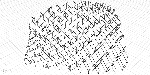
I studied the interlocking joint details in Grasshopper here and here. This time, the interlocking structures were revisited with a cleaner code and an in-depth explanation. I believe that this is a very good educational exercise for learning the potential of the native Grasshopper components.
The Preparations
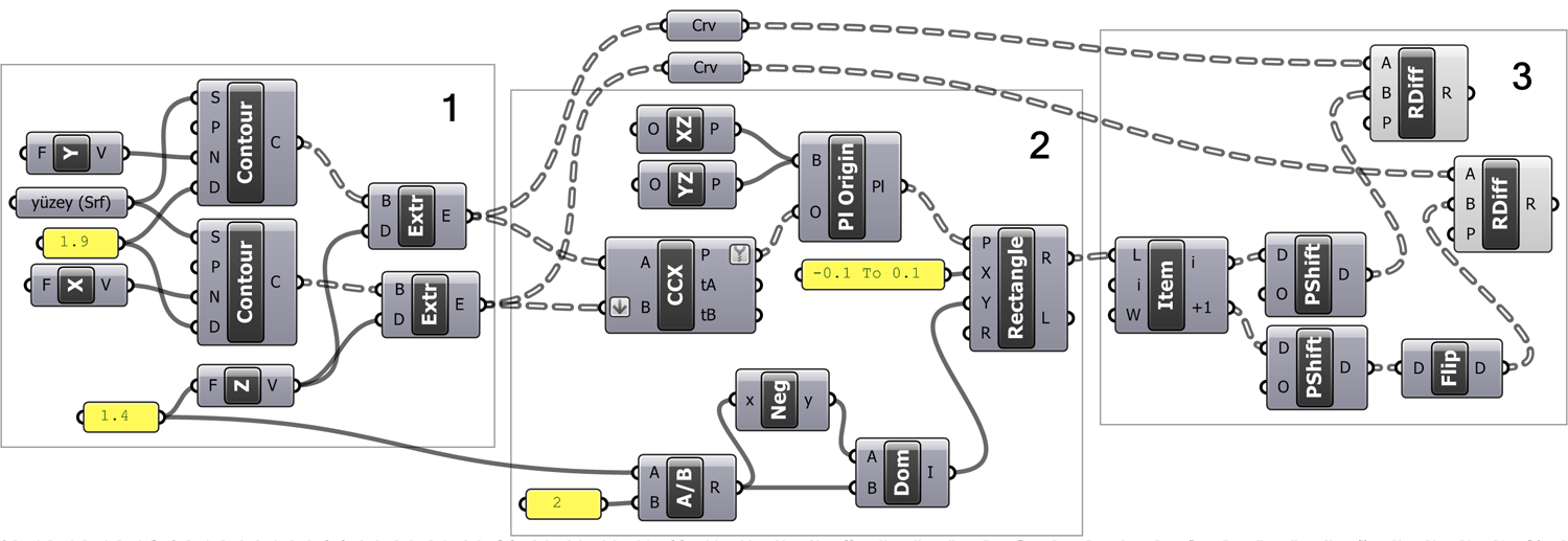
The Region Difference (RDiff) component is used to create the interlocking detail of a surface that is contoured with bi-directional spacing. In the first part of the code, after contouring our surface in two different directions (X and Y), we turn the curves into surfaces by Extrude (Extr). The vector components are used as the inputs of the Contour component. When you want to use different surfaces in this component, you can use, for example, Y and Z vectors instead of X and Y vectors depending on the direction of the reference surface.
Finding the Intersections
In the second part of the Interlocking Structures Revisited code, our aim is to find the points where the contour surfaces we have just produced intersect each other and to draw closed rectangular shapes facing those points in the right direction. These rectangles will then be subtracted from the contour lines with Region Difference (RDiff). We need to find the planes on which to draw our rectangles. The Rectangle component expects a plane and dimensions in the X and Y directions. We should place two of these rectangles for each intersection of the contour surfaces. One should be at the bottom and the other at the top. So that they are parallel to the contour surfaces. So that when we subtract these from the two contour surfaces, gaps can fit into each other perfectly.
Now, let’s find these intersection points. We intersect the contour surfaces we obtained with the help of Curve I Curve (CCX). We connect our contours in two directions to the A and B inputs of the Curve I Curve (CCX). The two Extrude (Extr) operations create our contour surfaces in separate branches. When we connect them to A and B as they are, they will not produce all the intersections we want. Therefore, the B input of the Curve I Curve (CCX) component is put into the Flatten operation (downward arrow shape). So we match each element in A with all the elements in B.
Drawing the Interlocking Structures Details
We must convert the points into planes facing the right direction. If you want to examine the data structure, you can connect a List Item (Item) to the P output of the Curve I Curve (CCX). Index 0 gives the points in the top row, and index 1 gives the points in the lower row. Our contour directions were the predefined X and Y directions. It is possible to control these directions parametrically, but it is easier to keep the directions constant and rotate the surface itself if possible and necessary. We will define our planes using our two contour directions and the axis, pointing upwards in the Z direction. In this case, the planes we need are Plane XZ (XZ) and Plane YZ (YZ). The Plane Origin (Pl Origin) component changes the origin of a plane.
When we enter more than one point in this component, we copy the plane. The intersection points we just obtained were in the form of data branches with indexes 0 and 1. Input B of the Plane Origin (Pl Origin) component takes the plane to be copied by changing its origin. First, we connect the XZ plane to this input. Thus, we copy planes in the XZ direction to the top points of the intersections. Then, by pressing shift from the keyboard, we connect the YZ plane to the B input of Plane Origin (Pl Origin). This will copy the YZ plane to the lower intersection points at index 1 of the points. You can observe all these developments by turning the components on and off.
Drawing the Rectangles
Now we must draw rectangles at the midpoints of these planes. Play with the components that determine the dimensions of the rectangles and examine which one works for what. Since we will perform boolean subtraction using rectangles, they must be slightly larger than the contours. As the contours of our surface become sharper, this excess will need to be even greater in order to be able to cut the contours nicely. Since the locations and directions of the rectangles are correct, we leave you to play with their sizes and continue with the third section.
Two-dimensional Boolean Operations
In the last part of the Interlocking Structures Revisited, we are using the Region Difference (RDiff) component. The rectangles we just created are extracted from the contour surfaces. Again, we require some data trickery to get the right rectangle out of the right contour. If you remember, as a result of the initial Extrude (Extr) operation, our contours formed separate branches. We convert the results of these two Extrudes (Extr) by connecting a Curve (Crv). The Region Difference (RDiff) component takes closed curves from which to extract something from input A, and shapes to output to input B.
In short, we will connect our contours to input A and rectangles to input B. It may also be possible to do this using a single Region Difference (RDiff). But for clarity, we will use two components for our two separate contour directions. If we examine, the rectangles facing XZ at index 0, and the rectangles below facing YZ at index 1. First of all, we separate the items with index i (0) and i+1 (1) with the List Item (Item) component.
Finishing the Interlocking Structures Revisited
If we try to make Region Difference (RDiff) with our contour sheets as it is, only one operation is done. From this, we understand that we must do the subtraction to match more than one rectangle versus one contour. When we examine the data structure of the 0 index rectangles, we can see that although they form a separate branch, their addresses progress in the form of {0;1}, {0;2}, {0;3} … {1;1}. This data structure was the product of Curve I Curve (CCX) in section number two when we intersect the contours.
The data structure we need is not to obtain each rectangle separately but to obtain the rectangles in the same order in the form of an aggregate data list. The Shift Paths (PShift) component that we use at this stage takes the data tree and gathers its elements in one level higher branch. Now, these data lists contain the rectangles in each row, and as a result of the Region Difference (RDiff) operation, all our subtraction in one direction is complete.
The Flip Matrix
So why did we put a Flip Matrix (Flip) for the second subtraction? In our first subtraction, the direction of our contour curves was the same as the direction of rectangles. To observe this, connect a Tree Branch (Branch) to a Construct Path (Path) component and make I 4 or 5. If you connect Shift Paths (PShift) to the T input of the Tree Branch (Branch) component, you will see that all the rectangles in the 5th path are already on the same plane as the subtracted contour curve.
Now if you connect the other (bottom) Tree Branch (Branch) to the same T entry this time, you will see that the bottom rectangles come in the same order. Although this may not seem like a problem, most of the rectangles with this data structure miss our second contour curves. These are actually facing exactly ninety degrees to the first. The Flip Matrix (Flip) component comes to our rescue. It flips the rows and columns of the data structure of our rectangles in opposite directions. If you connect the data from the Flip Matrix (Flip) this time to the T input of the Tree Branch (Branch), you will see that you lined up the rectangles parallel to the contour curve.
Cite this post
Related Posts
Interlocking Structure with Boolean
August 23, 2026
You are seeing the last of the interlocking system trials that I have previously tested in two exercises. If you remember, in our first trial, we were drawing interlocking joinery details on cross-sections using closed curves, without any solid modeling. And here is the most advanced one, I guess. In this exercise, however, we are creating a solid model that incorporates these interlocking details. This time, we will look at how to construct the same system using Boolean operations. Boolean…
Voronoi Cage
June 26, 2023
I have created a straightforward Grasshopper code that generates a Voronoi diagram on a surface. Then, it adds thickness to form a structure called a “Voronoi Cage.” In the initial step, I project a surface onto the ground plane (Z=0). The projected frame serves as the boundary for two operations: generating random points using the Populate 2D (Pop2D) function and calculating the Voronoi diagram based on these points. The resulting Voronoi cells are then slightly offset inwards. Moving on to…
Interlocking Structure Between Two Surfaces
January 29, 2012
A previous work showed a method to create interlocking structures to be created without boolean operations. This time, a small addition is made to create waffle objects using two surfaces, one is the top surface, and the other is the bottom. It was a small modification at the beginning; to replace the “extrude” component with an “edge surface” component. But the interlocking details are now different at each intersection, so another modification is made to the drawing of the rectangles….
Interlocking Structure (No Boolean)
January 2, 2012
It has been a tough problem for me, for the last two days. A parametric model of an interlocking structure (sometimes also called egg-crate, waffle, or contouring structure) can be created easily in Grasshopper using a Contour component. In addition, you need a couple of list management operations and a boolean (or region) difference event. However, Rhino and Grasshopper are very slow at calculating boolean differences on both solids and surfaces. Fabrication models of such structures don’t have to be…
Open Nest
July 24, 2023
In this short trial, I will be testing the Open Nest add-on for Grasshopper. The add-on is available in food4rhino as of 2023. For this test, I will use the latest exercise on Interlocking structures I experimented with here. Nesting is an important topic, especially in today’s economic crisis. It reduces the waste materials on laser-cut plates. First, I should re-visit the interlocking structures Grasshopper definition here. The below image is the new definition for the interlocking structure: The new…