
Interlocking Structure with Boolean
You are seeing the last of the interlocking system trials that I have previously tested in two exercises. If you remember, in our first trial, we were drawing interlocking joinery details on cross-sections using closed curves, without any solid modeling. And here is the most advanced one, I guess. In this exercise, however, we are creating a solid model that incorporates these interlocking details. This time, we will look at how to construct the same system using Boolean operations. Boolean algebra is a very broad set of logical operations used across many different fields. I recommend checking out this Wikipedia article about it.
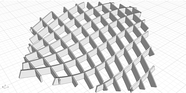
In the first section of this exercise, we draw rectangles on defined perpendicular planes on a surface from which we took contours, then convert them into surfaces using the Sweep1 (Swp1) component, and then turn them into solid objects with the help of Cap Holes (Cap). At the end of this section, we should have the beams without interlocking details. These beams must be in the form of a data tree with separate branches in two directions. In section two, all intersection points of our contours with one another are identified using the Multiple Curves (MCX) component. Then, two boxes are drawn at each of these points. If you recall when we did the same exercise on 2D cross-sections, we drew pairs of rectangles at this stage. This time, we will use Boolean operations for solids while subtracting these drawn boxes from our beams in the correct order.
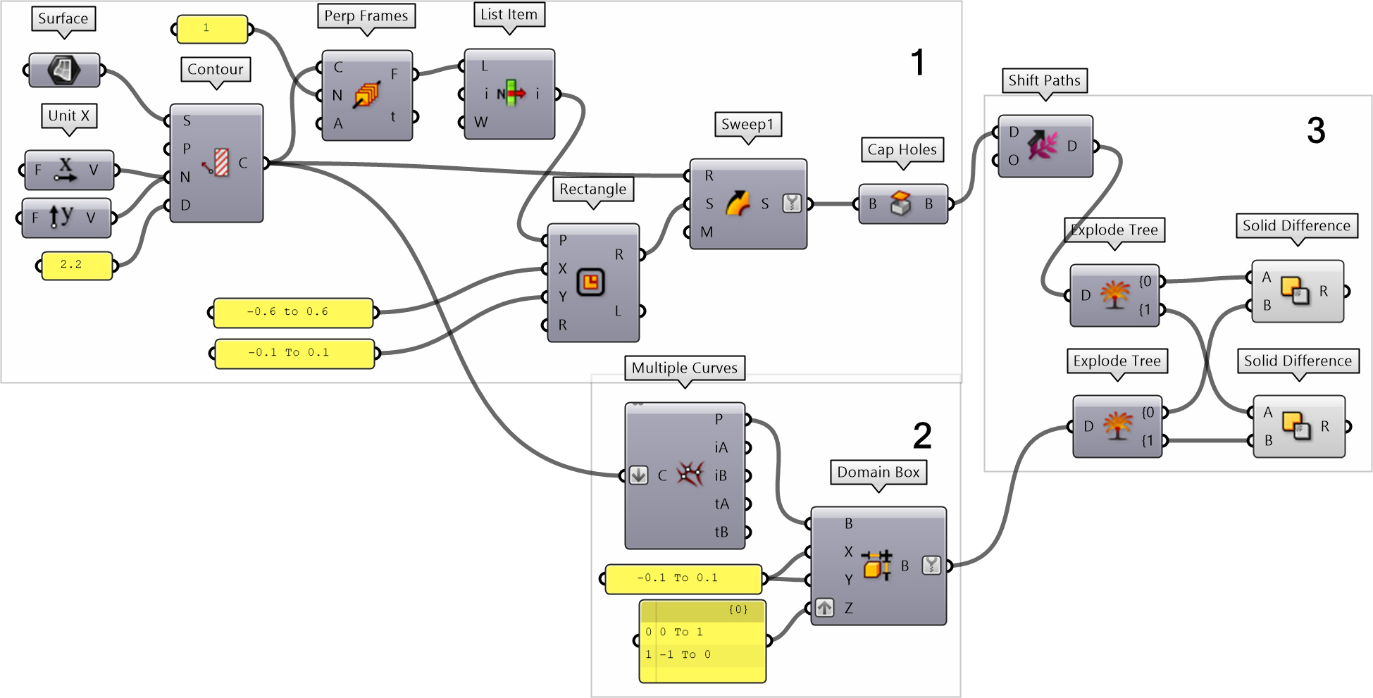
In section three of the exercise, the subtraction process is carried out. For this, a Solid Difference (SDiff) operation is performed between the branches of the data trees exploded using Explode Tree (BANG!). Connect a Panel to inspect which box is being subtracted from which beam. You can see that the data tree holding the beams first undergoes a Shift Paths (PShift) operation. Through this, beams in both directions are split into separate branches and prepared for the explosion process. On the other hand, because boxes were drawn in pairs from the single flattened list coming from the Contour operation, they have formed a data tree with two branches.
For some reason, I have never been able to properly use the Region Slits (RSlits) component developed for similar interlocking systems. In the future, we might model another interlocking system using that component set.
Cite this post
Related Posts
Interlocking Structure (No Boolean)
January 2, 2012
It has been a tough problem for me, for the last two days. A parametric model of an interlocking structure (sometimes also called egg-crate, waffle, or contouring structure) can be created easily in Grasshopper using a Contour component. In addition, you need a couple of list management operations and a boolean (or region) difference event. However, Rhino and Grasshopper are very slow at calculating boolean differences on both solids and surfaces. Fabrication models of such structures don’t have to be…
Interlocking Structures Revisited
April 10, 2023
I studied the interlocking joint details in Grasshopper here and here. This time, the interlocking structures were revisited with a cleaner code and an in-depth explanation. I believe that this is a very good educational exercise for learning the potential of the native Grasshopper components. The Preparations The Region Difference (RDiff) component is used to create the interlocking detail of a surface that is contoured with bi-directional spacing. In the first part of the code, after contouring our surface in…
Open Nest
July 24, 2023
In this short trial, I will be testing the Open Nest add-on for Grasshopper. The add-on is available in food4rhino as of 2023. For this test, I will use the latest exercise on Interlocking structures I experimented with here. Nesting is an important topic, especially in today’s economic crisis. It reduces the waste materials on laser-cut plates. First, I should re-visit the interlocking structures Grasshopper definition here. The below image is the new definition for the interlocking structure: The new…
Testing the Nesting
May 28, 2012
Here I am testing the nesting. RhinoNest is a plug-in for Rhino and a set of components for Grasshopper. I tested it using my old interlocking fabrication definition (here) and (here). I downloaded RhinoNest from this website and installed it. However, I sounded a little complicated at first sight. Then I found a sample definition (here) and modified it a little bit to meet my purposes. First of all, I added orientation components (grey group below) to align all sections to the WorldXY…
Voronoi Cage
June 26, 2023
I have created a straightforward Grasshopper code that generates a Voronoi diagram on a surface. Then, it adds thickness to form a structure called a “Voronoi Cage.” In the initial step, I project a surface onto the ground plane (Z=0). The projected frame serves as the boundary for two operations: generating random points using the Populate 2D (Pop2D) function and calculating the Voronoi diagram based on these points. The resulting Voronoi cells are then slightly offset inwards. Moving on to…