Tool Calibration in Robots
by Tuğrul Yazar | October 11, 2018 11:34
On the second day of the Digital Fabrication course, we tried to understand what is a “tool” and how to draw/ produce/ attach/calibrate a simple penholder tool for our robot. This study will hopefully make students aware of the effects of these procedures in robotic design and fabrication.
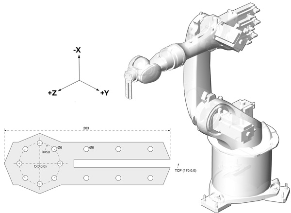
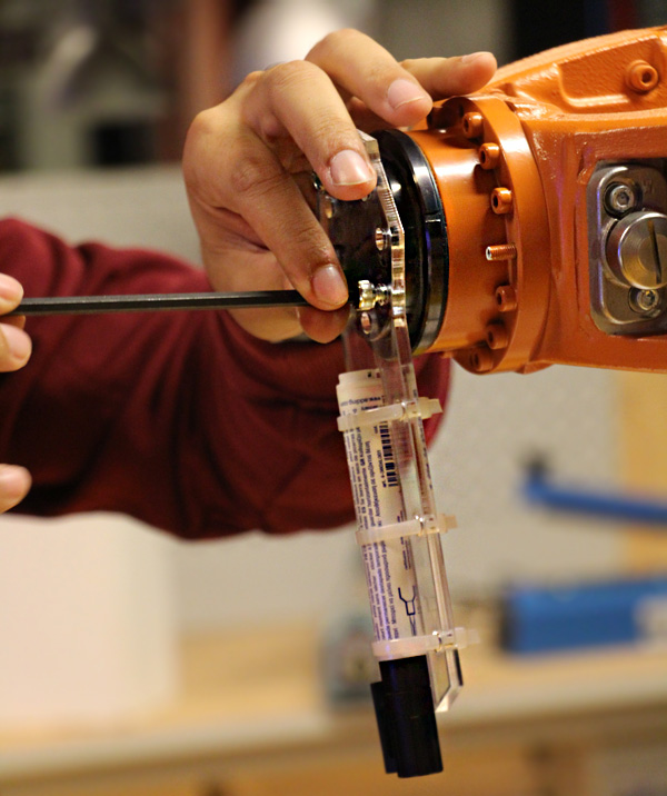
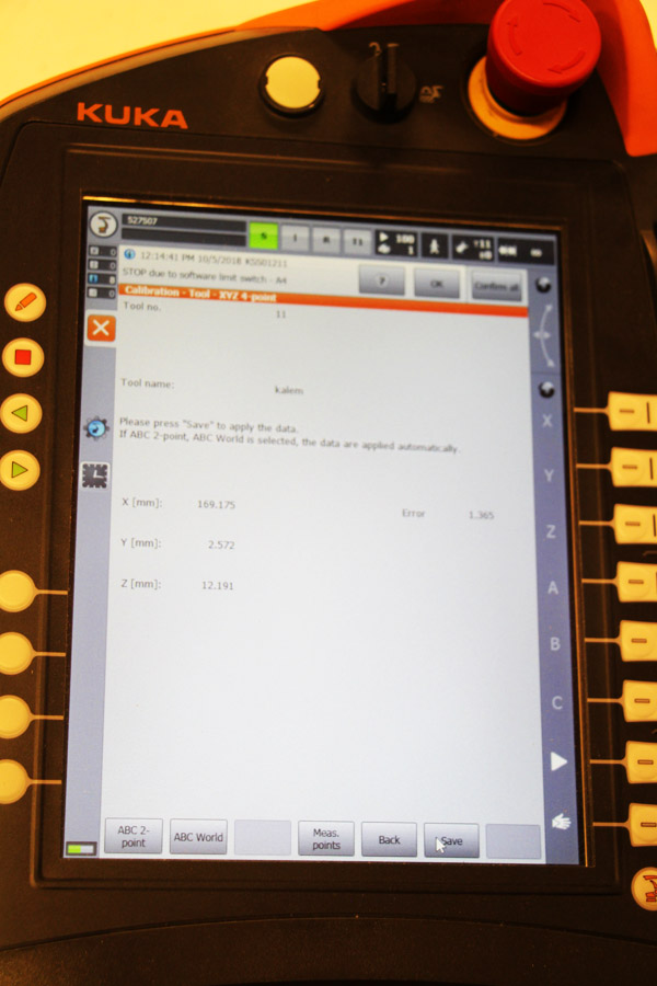
The tool we used here is based on this Rhino drawing[1] laser-cut from a waste plexiglass sheet. The flange of our robot has a diameter of 50mm and has 8 holes for screws with a 6mm diameter. I also left some other holes to fix a pen with zip ties. In the exercise, first, we familiarized ourselves with the axis and Cartesian motions via smart pad. After remembering the last week and getting comfortable with the manual jogging techniques, we calibrated the penholder tool by using the 4-point method described in the robot’s manual.
We analyzed the drawing of the tool and determined a TCP (tool center point) position, which is precisely 170mm far from the flange center. This drawing also constitutes the front view of the flange coordinate system. After calibrating the tool by using the 4-point method, we checked the calculated position of the TCP (should be less than 2mm.) Also, check the position of TCP by placing a point on that coordinates in Rhino. Kuka calculated the TCP as 169.1 mm far from the flange center. This is less than a millimeter and perfectly enough for us.
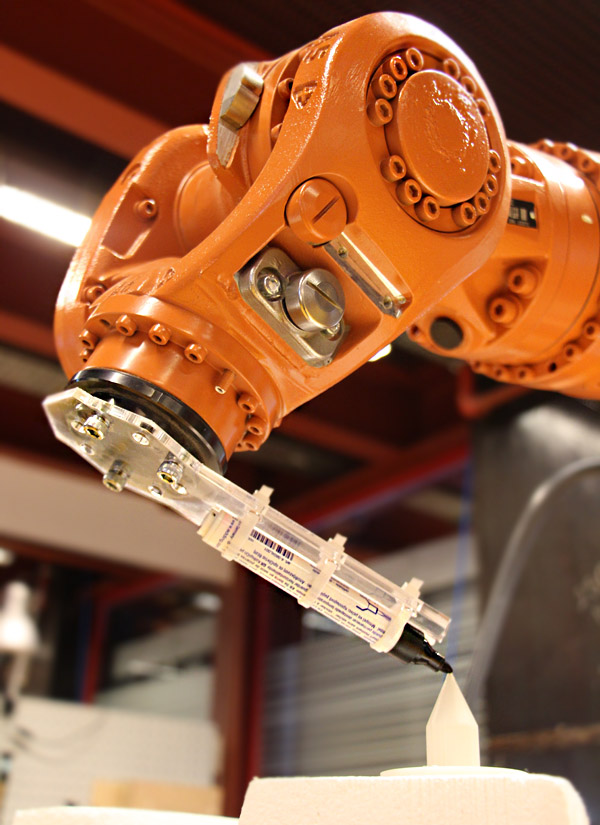
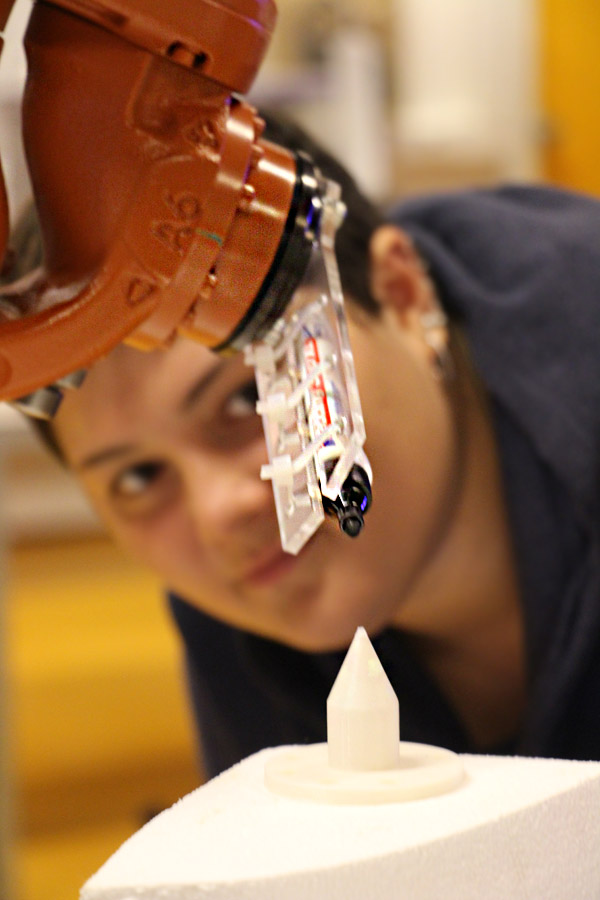
We used the tool coordinate system for manually jogging the robot. If the calibration is correct, the robot should be able to move towards its flange direction by Z-axis and towards the direction of the penholder by the X-axis. Finally, we tried to draw points and lines on various foam board surfaces by using those axes.
- this Rhino drawing: https://www.designcoding.net/decoder/wp-content/uploads/2018/10/kalemlik.3dm
Source URL: https://www.designcoding.net/df-day-2-tool-calibration/